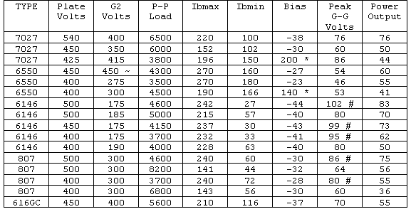
*=Cathode bias resistor value in ohms.
~=ultralinear operation: screens connected to taps at 43% of AC plate voltage.
#=Class AB2 operation
Table 1. Operating Parameters For Various Tubes.
I have always preferred the sound qualities of tube type audio equipment. I also prefer moderately loud music in my vehicle. The store-bought solution typically comes with a price tag of about $2000. The following description of the design and construction of a mobile audio power amplifier using vacuum tubes in a mixture of old and new technology should serve as a guide for those wishing to perform a similar experiment.
In order to choose the best combination of components for the amplifier, A table was compiled from the data in various tube manuals so that it was easy to visually compare the different parameters. I happened to have on hand a pair of used Dynaco A-430 transformers, which have a 4300 ohm center-tapped primary as well as screen-grid taps. A pair of type "D-104" 12-volt dynamotors (Fair Radio Sales, Lima, OH.) producing 400 volts at 180 ma., continuous duty were used for the B+ supply. These parts already on hand dictated which of the tubes in table 1 would be best suited. Since drive requirements for class AB2 in any of these cases is only about 300 mw, It was decided to take advantage of the increased efficiency and power output available from this class of operation. For AB2 operation, the grids are driven positive during part of the audio cycle and therefore the peak grid to grid voltage value is greater than the bias voltage. Transformer coupling was used on the inputs to maintain good regulation of the drive signal. 10 watt "universal line-to-voice coil" transformers work very well in this application, being a good compromise between bandwidth and size. The transformers have tapped primaries, as well as multi-tap secondaries, enabling a step-up ratio of about 1:43 so that the amplifier can be driven with 2-5 volts RMS. 6146's were chosen because they are designed for linear amplifier operation while having a low idling current, low screen grid voltage, and high power output in AB2 mode. The "ultra-linear" screen-grid taps on the output transformers were not used. If one prefers ultralinear operation, 6550's are the best choice, but they require more plate current than the dynamotors are rated for.
*=Cathode bias resistor value in ohms.
~=ultralinear operation: screens connected to taps at 43% of AC plate
voltage.
#=Class AB2 operation
Table 1. Operating Parameters For Various Tubes.
The 6146 requires 175 volts for the screen grid, but can use up to 250V. A series arrangement of an 0D3 and an 0C3 regulator tube, normally used as shunt regulators, was placed in series with the plate supply and the screen grids. Although the screen voltage is not regulated perfectly, and fluctuates with plate voltage, this is an easy and reliable way to provide a voltage within acceptable limits without adding another power supply. The no-load voltage from the dynamotors is about 500 volts, so the 150 volt drop across the 0C3 and the 100V drop across the 0D3 results in about 250 volts at the screen grids. A 40 uF capacitor connected across the regulator tubes reduces high-frequency noises otherwise present on the screen grids at high audio levels. To further reduce distortion at a slight cost in decreased gain, 34K 1% resistors are used in a balanced feedback arangement. If you do not know which polarity the transformers are, the correct connection is the one which gives the least gain. Both the inputs and the outputs are left floating in this design, which accommodates most modern car stereo systems. Note that in this case the output terminals are at bias voltage potential, and should not be grounded, not because it would upset the bias excessively, but rather because it would degrade the balanced feedback arrangement. The overall schematic of the amplifier is shown in figure 1.
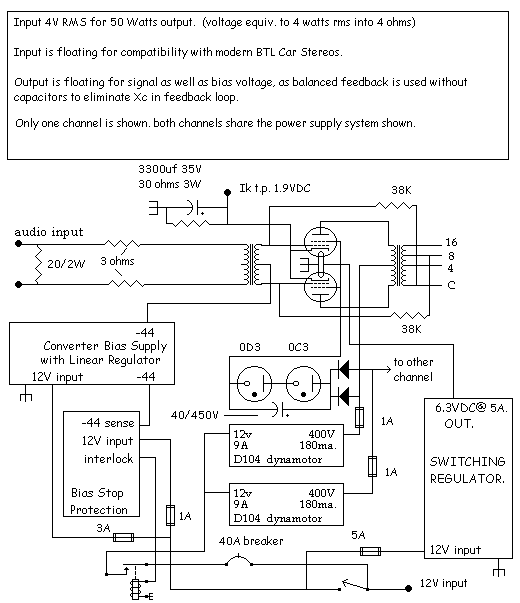
Figure 1. Overall Schematic Diagram.
If you have a pair of output transformers with a 25V center tapped line output winding in addition to the 4/8/16 ohm winding then you are in luck, and can use the special output circuit in figure 1a. With this circuit, the 38K ohm feedback resistors are optional, as current feedback is applied to the cathodes of the tubes. This configuration improves the linearity of the amplifier greatly and is similar to that used in some McIntosh amplifiers in years past.
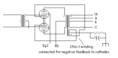 Figure 1a. Improved Output Circuit.
A bias voltage is required for the tubes. Rather than use another dynamotor, A small converter was designed around a surplus 400Hz power transformer, as shown in figure 2. A 555 timer drives an amplifier connected to the 12V, 1A secondary of the transformer. The 115V primary is then used as the secondary, where a rectifier and filter produces -95 volts DC. A linear regulator allows adjustment of the bias voltage to -44V. The reason for using a 400 Hz transformer is that such transformers are much smaller for the same power rating than their 60Hz relatives. Even so, the transformer is operating at only 1/4 of its normal power rating. A well-regulated low-impedance bias supply is required for class AB2 operation, since grid current is drawn. The two adjustment potentiometers marked Freq1 and Freq2 are used to set the ON time of the switching transistor to minimum, which is about 60% duty cycle, and to adjust the frequency to 2 KHz. Neither is critical, as long as the duty is around 50% and the frequency is adjusted for maximum output. An optional protection circuit interlock may be used to keep the dynamotors from energizing in case bias is lost.
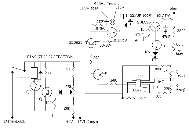
Figure 2. Bias Power Supply And Protection Circuit.
The four 6146 tube heaters require 6.3 volts DC at 5 amps total. Heater voltage is an important factor in tube life. The vehicle's electrical system can vary from 12 to 14.5 volts, therefore, a simple dropping resistor would not provide correct heater voltage under all circumstances, in addition to generating 30 watts of heat. A buck-type switching regulator was designed, and is shown in figure 3. A goal was to avoid the necessity of using special IC's and complicated circuitry. The inductor is a surplus 1mh, 8 amp unit. Several inductors were tried, and 500uh to 2mh ones worked well also. An important aspect of the construction of such a regulator is that the wiring shown in bold should be heavy-gauge wire, such as #12. A low impedance path for current from the negative end of the input capacitor C1 to the diode D1 is essential to stability. The regulator works as follows: When power is applied, there is no voltage present at the output, and the reference voltage across the 4 diodes is 2.5V. Because of this, the op-amps, which are operated in open-loop for maximum gain, present a high voltage level at pin 1. This turns on the Darlington-connected pair of Q2 and Q3, which turns on Q1. Voltage from the 12V supply is presented to L1, and current begins to flow through L1, charging C2 and providing power to the load. As soon as the load voltage reaches 6.4 volts, pin 6 of the op-amp exceeds 2.5 volts by a few millivolts, and the op-amp's output at pin1 goes to near zero volts. This turns off Q2, Q3,and Q1. Current has been flowing in L1 and now that Q1 has turned off, the voltage at the collector of Q1 would go very negative due to the imminent collapse of the magnetic field of L1, possibly damaging Q1, if it were not for the diode D1. D1 provides a path for L1's decreasing current flow until Q1 is turned back on. Now, with Q1 off, the load voltage drops to 6.2 volts. The voltage presented to the op-amp pin 6 is now a few millivolts less than the 2.5 volt reference, and the op-amp again brings its output on pin 1 high, starting the process over. The frequency of operation is about 40 KHz and the efficiency is 90%. The key to this efficiency is to saturate Q1 during its ON time, reducing its dissipation. The 3.3K resistor in the low side of the error amplifier divider chain may need trimming in order to allow the 500 ohm pot to adjust the output over the range of 5-7V. In the case examined here, a 22K resistor was placed across the 3.3K resistor. The heater voltage should be 6.3V +/- 5%, per the RCA Transmitting Tube Manual. Note that the measured heater supply waveform is a square wave, rather than a DC voltage. The frequency and duty cycle vary slightly but the averge output voltage remains reasonably constant. Purists may wish to add a filter section comprised of a 1mh inductor in series with the heaters, bypassed by a 10,000uf capacitor. In that case, the voltage feedback connection should remain directly at the 'unfiltered' output of the 500uh inductor to assure stable regulator oscillation.
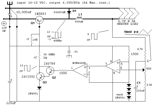
Figure 3. Heater Power Supply Circuit.
Although heatsinks with 80 square inches of area were used for the heater and bias supply switch devices and mounted under the chassis, the devices dissipate so little heat that they could be bolted directly to the chassis. It was desired to "hide" any solid-state devices from the external appearance of the amplifier.
The relay which turns on the amplifier is actually two 30-amp "Bosch" type automotive relays in parallel. This was done because the peak starting current of the dynamotors is in excess of 60 amps for a few milliseconds.
The whole amplifier was built on a 15"x17"x3" aluminum chassis recycled from another piece of equipment. Ceramic feedthroughs and hardware make the 500V plate cap connections safely. Each pair of tubes has its cathodes returned to ground through a 30 ohm resistor bypassed with a 3300 uF Capacitor. 0.81 volts at this test point is equal to 27 ma idling current as called for in the table. Some actual measured values during operation are shown in the table below. The idling current was increased to 57ma. to reduce crossover distortion. This increase to 12.5 watts quiescent anode dissipation per tube is still well within the 20 watt rating for the 6146. Note the heater voltage was low during the data acquisition. It was subsequently set to 6.25VDC. Although not shown in the table, the amplifier draws about 11 amps when idling.

Table 2. Measured Operating Conditions
A large terminal strip along the front serves for all external connections. Dynamotors require periodic lubrication (every 1000 hours, or about once a year if you drive for 2 hours a day) so be sure to avoid my mistake and mount then so that you can remove the end bells and service the bearings. Dynamotors make a physical whine as they spin at 4000 RPM. The trunk is a good place for the amp, but if you have a large van like I do, you might want to enclose it in a cork-lined box, with just enough opening for a good exhaust fan and intake port. I mounted a 4' standard "BUD" rack in the van right behind the cargo cage, and then rackmounted the amp. I now have plenty of rack space left for other upcoming projects! I used reworked home speakers with 2.2 cubic ft. boxes, 12" woofers, 5" mids, and horn tweeters. It cranks and sounds great!
Images
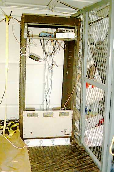 The 4 ft. rack mounted in the test vehicle. A 100 amp power cable
runs from both the positive and negative battery terminals to the rack.
The 4 ft. rack mounted in the test vehicle. A 100 amp power cable
runs from both the positive and negative battery terminals to the rack.
 The front panel removed, showing the terminal strip. A strip with
#10 screws was used due to the high currents.
The front panel removed, showing the terminal strip. A strip with
#10 screws was used due to the high currents.
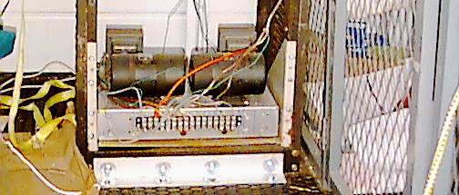
 Oblique chassis view. The three terminals at the rear of the chassis are
for checking the idling current of the output tubes.
Oblique chassis view. The three terminals at the rear of the chassis are
for checking the idling current of the output tubes.
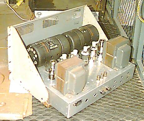
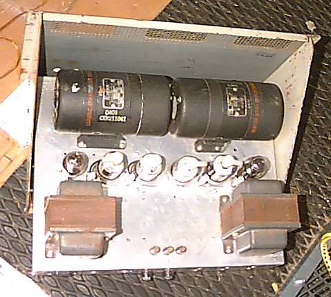 Top view. Showing placement of dynamotors, tubes, and output transformers.
The two tubes on the ends are the regulators.
Top view. Showing placement of dynamotors, tubes, and output transformers.
The two tubes on the ends are the regulators.
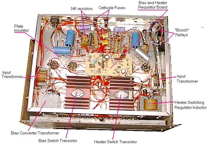 The components were arranged underneath the chassis to allow easy access.
Even so, there is not much extra room for additions.
The components were arranged underneath the chassis to allow easy access.
Even so, there is not much extra room for additions.
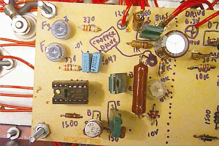 The bias converter oscillator and driver are mounted on one half of a home made
printed circuit board. Note the two pots for "freq1" and "freq2" The upper large
green 2SB825 transistor is the chopper driver, and the lower two are the linear
regulators. The regulator error amp did not have to be so large a transistor, but
I had no other high voltage pnp transistor handy.
The bias converter oscillator and driver are mounted on one half of a home made
printed circuit board. Note the two pots for "freq1" and "freq2" The upper large
green 2SB825 transistor is the chopper driver, and the lower two are the linear
regulators. The regulator error amp did not have to be so large a transistor, but
I had no other high voltage pnp transistor handy.
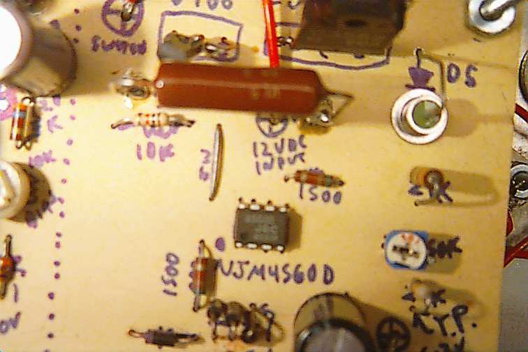 The Heater switching regulator and driver. The large diode shown as
D5 is in the emitter circuit of the 2SC3552, and is a high speed diode.
The 1N4001 called for in the schematic was too slow and caused
heating problems with the 2SC3552. The voltage is adjusted with the pot
marked "50K", but it is a 500 ohm as shown in the schematic. The large
brown resistor is the 30 ohm 3 watt unit. The 2SC3552 is the large black
transistor right above it. The 2SC3552 needs no heat sink.
The Heater switching regulator and driver. The large diode shown as
D5 is in the emitter circuit of the 2SC3552, and is a high speed diode.
The 1N4001 called for in the schematic was too slow and caused
heating problems with the 2SC3552. The voltage is adjusted with the pot
marked "50K", but it is a 500 ohm as shown in the schematic. The large
brown resistor is the 30 ohm 3 watt unit. The 2SC3552 is the large black
transistor right above it. The 2SC3552 needs no heat sink.
 The surplus 400Hz transformer which was used for the bias converter was
well made, and probably overkill by a factor of about 5 for this purpose.
The surplus 400Hz transformer which was used for the bias converter was
well made, and probably overkill by a factor of about 5 for this purpose.
After 2 months of operation, no measurable changes were noted in the amplifier's characteristics. Although any noise artifacts generated by the power supplies were inaudible, purists might complain about the 1-3 millivolts of noise present across the output terminals. More attention to layout and heater power supply filtering would probably address that complaint. Possible improvements might be a switching power supply for the B+, replacement of the input transformers with tube driver circuitry, and higher plate voltages where permitted by output transformer ratings. An extra saftey feature would be to change the plate supply fuses to 500ma and place them in the cathode return paths, avoiding screen current runaway in the event of the fuse blowing. After one year of operation, the unit was removed from the test vehicle and examined. One end of a tubular electrolytic capacitor had come loose from vibration but apparently had little effect on the sound.
Lastly, this project uses dangerously high voltages with high currents and should be attempted with great caution and by experienced persons. The 500 volts output from a dynamotor is deadly, as can be the 200 volt screen grid supply. Vacuum tubes can reach high temperatures of 200 degrees centigrade as well, causing burns if touched. Enjoy!